| Administrator Handbook | Table of contents |
|
The RFC 1213 contains SNMP object definitions, which have to be implemented in any agent to be compatible with the MIB 2 standard.
This standard describes a set of objects sorted by protocol type of level 1 up to level 4 from the OSI model.
The next paragraphs will explain how to use them through examples. We will use a� router as device for a better understanding.
LoriotPro provides several tools allowing the collect of the SNMP agent’s objects. Look at the corresponding chapters to have a detailed description of their use.
A detailed description of the MIB 2 is out of the scope of this guide, refers to� to RFC 1213 or to the book listed in annex.
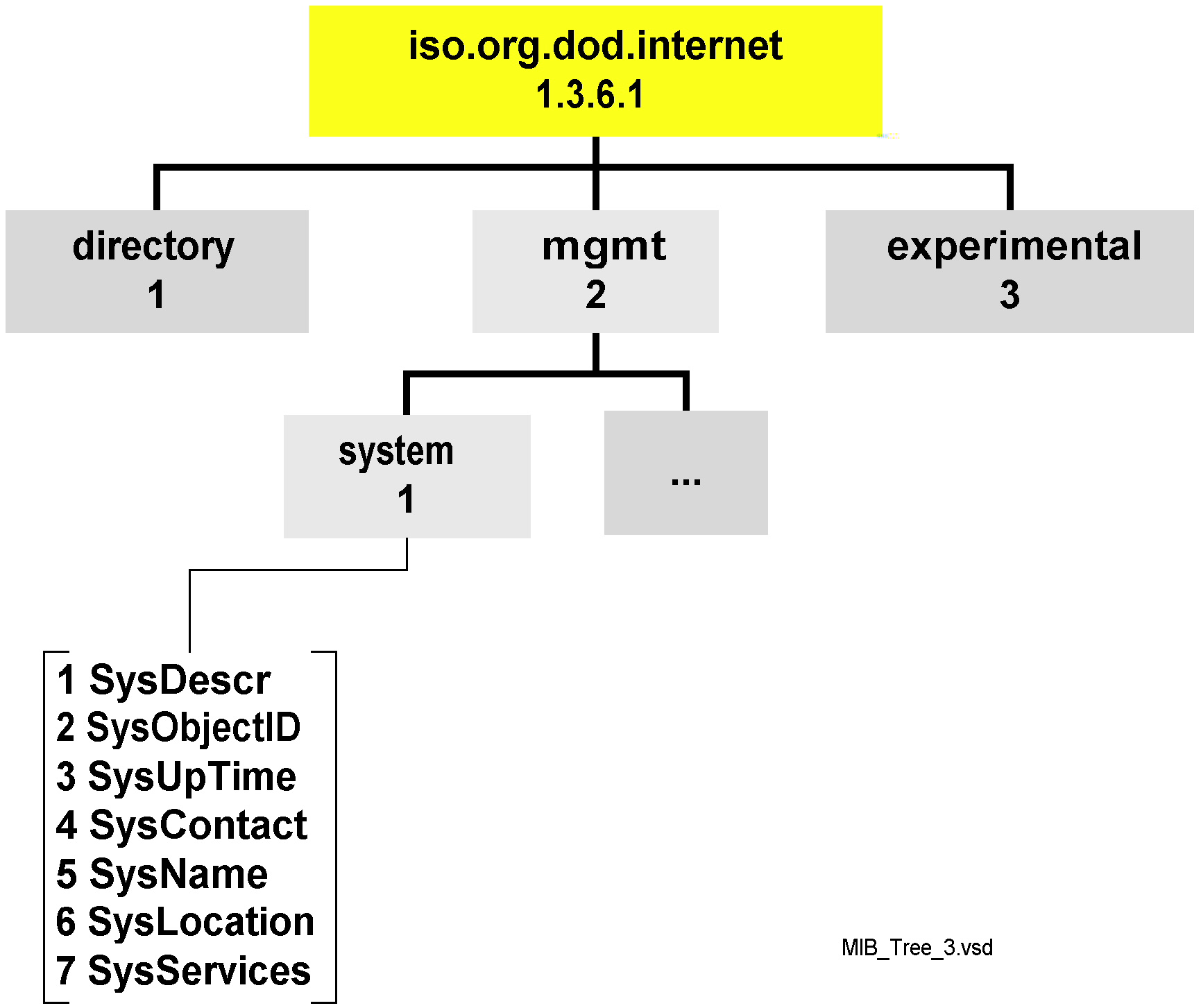
This is common view of the MIB tree and branch mib-2 defined in the RFC 1213 as you can see it with LoriotPro
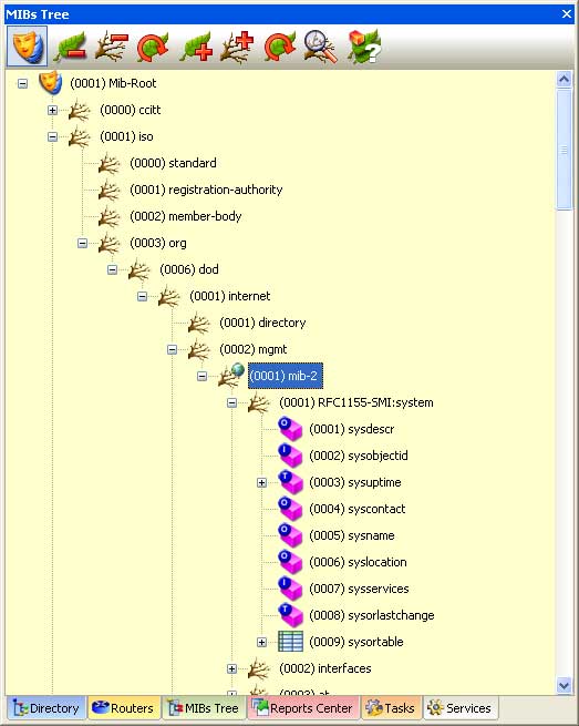
From the MIB tree window, it is possible to collect one by one the value of any agent’s object. Double click in the MIB tree on the desired object and the software will automatically shows you the values, depending on the object type, either in an information window or in a table window.
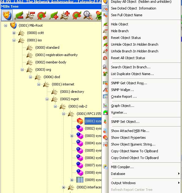
To obtain information on a SNMP object from the MIB tree use the contextual menu (right click) and select the ‘Get Mib File’ option. This will show you the object description contained in the MIB file.
 �.
�.
The System group contains a set of objects describing the equipment, which built it, which type and model, the location in the network …
The group system has 7 objects, and their implementation is mandatory in all agents.
This group is fully described in the MIB to make you familiar with the concept.
This object is a character string that should describe the agent. This information could include the full agent name, his version and or identification number, which operating system is running on, etc.
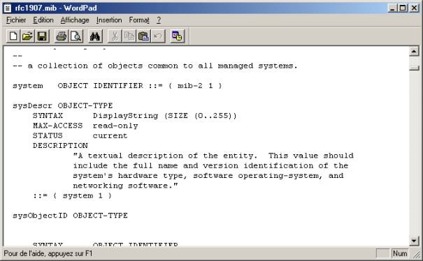
��������� sysDescr OBJECT-TYPE
������������� SYNTAX� DisplayString (SIZE (0..255))
������������� ACCESS� read-only
������������� STATUS� mandatory
������������� DESCRIPTION
��������������������� "A textual description of the entity.�
This value
��������������������� should include the full name and version
��������������������� identification of the system's hardware
type,
��������������������� software operating-system, and networking
��������������������� software.� It is mandatory
that this only contain
��������������������� printable ASCII characters."
������������� ::= { system 1 }
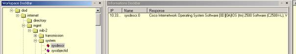
| sysdescr.0 |
Cisco Internetwork Operating System
Software* |
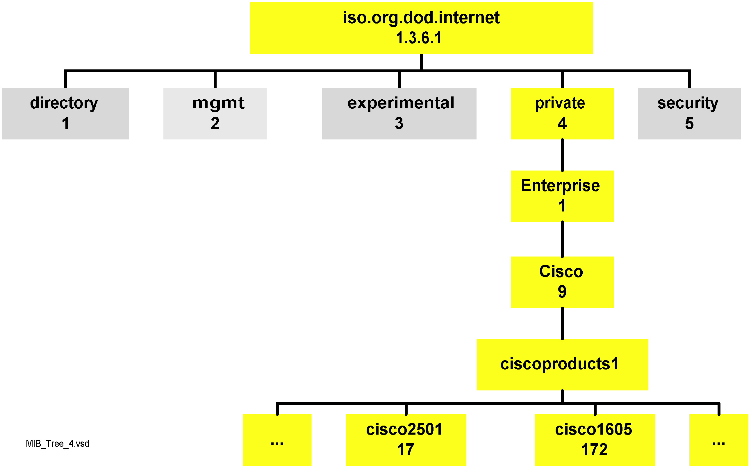
The OID (Object Identifier) allows the constructor to identify in a distinctive manner its object among others in the tree.
��������� sysObjectID OBJECT-TYPE
������������� SYNTAX� OBJECT IDENTIFIER
������������� ACCESS� read-only
������������� STATUS� mandatory
������������� DESCRIPTION
��������������������� "The vendor's authoritative identification
of the� network management subsystem contained in the
��������������������� entity.� This value is allocated
within the SMI enterprises subtree (1.3.6.1.4.1) and provides
an
��������������������� easy and unambiguous means for determining
`what � kind of box' is being managed.� For example,
if
��������������������� vendor `Flintstones, Inc.' was assigned
the subtree 1.3.6.1.4.1.4242, it could assign the
��������������������� identifier 1.3.6.1.4.1.4242.1.1 to its
`Fred� Router'."
������������� ::= { system 2 }
| sysObjectID.0 |
cisco.1.17 |
��������� sysUpTime OBJECT-TYPE
������������� SYNTAX� TimeTicks
������������� ACCESS� read-only
��� ����������STATUS� mandatory
������������� DESCRIPTION
��������������������� "The time (in hundredths of a second)
since the�� network management portion of the system was last��
re-initialized."
������������� ::= { system 3 }
��������� sysContact OBJECT-TYPE
������������� SYNTAX� DisplayString (SIZE (0..255))
������������� ACCESS� read-write
������������� STATUS� mandatory
������������� DESCRIPTION
��������������������� "The textual identification of the
contact person�� for this managed node, together with information
on how to contact this person."
������������� ::= { system 4 }
| sysContact.0 |
Henri Dupont |
��������� sysName OBJECT-TYPE
���������� ��SYNTAX� DisplayString
(SIZE (0..255))
������������� ACCESS� read-write
������������� STATUS� mandatory
������������� DESCRIPTION
��������������������� "An administratively-assigned name
for this� managed node.� By convention, this is
the node's
��������������������� fully-qualified domain name."
������������� ::= { system 5 }
| sysName.0 |
CiscoRouterP7 |
��������� sysLocation OBJECT-TYPE
������������� SYNTAX� DisplayString (SIZE (0..255))
������������� ACCESS� read-write
������������� STATUS� mandatory
������������� DESCRIPTION
��������������������� "The physical location of this node
(e.g., telephone closet, 3rd floor')."
������������� ::= { system 6 }
| sysLocation.0 |
B�timent 5, rue des Abeilles |
��������� sysServices OBJECT-TYPE
������������� SYNTAX� INTEGER (0..127)
������������� ACCESS� read-only
������������� STATUS� mandatory
������������� DESCRIPTION
��������������������� "A value which indicates the set of
services that� this entity primarily offers.
��������������������� The value is a sum.� This
sum initially takes the value zero, Then, for each layer, L,
in the range
���������� �����������1 through 7, that this node
performs transactions
��������������������� for, 2 raised to (L - 1) is added to the
sum.� For example, a node which performs primarily
routing
���� � functions would have a value of 4 (2^(3-1)).� In�
contrast, a node which is a host offering
��������������������� application services would have a value
of 72��� (2^(4-1) + 2^(7-1)).� Note that in the
context of
��������������������� the Internet suite of protocols, values
should be�� calculated accordingly:
�������������������������� layer� functionality
������������������������������ 1� physical (e.g.,
repeaters)
������������������������������ 2� datalink/subnetwork
(e.g., bridges)
������������������������������ 3� internet (e.g.,
IP gateways)
������������������������������ 4� end-to-end�
(e.g., IP hosts)
������������������������������ 7� applications (e.g.,
mail relays)
��������������������� For systems including OSI protocols, layers
5 and�� 6 may also be counted."
������������� ::= { system 7 }
| sysService.0 |
6 |
The following table will allow you to easily use these values.
| Services |
Level (OSI) |
Value (addition) |
|---|---|---|
| Application |
7 |
64 |
| Transport |
4 |
8 |
| Network |
3 |
4 |
| Datalink |
2 |
2 |
| Physical |
1 |
1 |
Example
If the device is a repeater, the value is 1 (physical).
If the device is a bridge, the value is 2 (datalink).
If the device is a router, the value is� 4 (network).
If the device is a bridge and a router, the value is 2+4=6.
In our example the equipment return the 6 value, it is the bridge router.
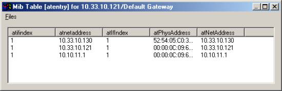
The interface group contains a table object giving information on all network interfaces available in the device. For each of them an instance of this object is used, instances are selected by an index number.
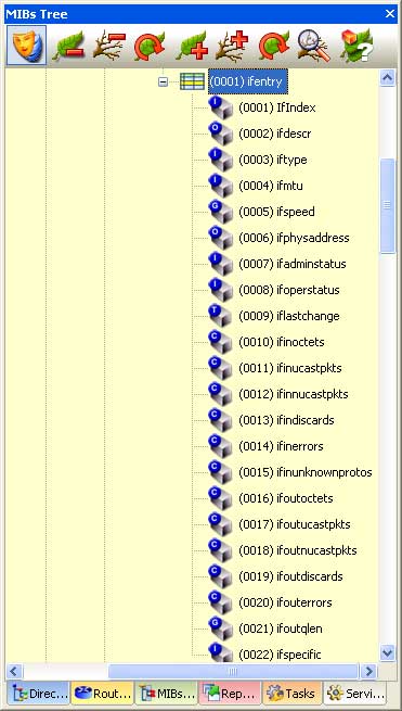
We will not describe here after each of these objects. The most common used are the ifinoctets and the ifoutoctects that stand for:
Interface Out Octets: total number of octets transmitted since last reset
Interface In Octets : total number of octets received since last reset
The table below has been get from the contextual menu for the ifentry object.
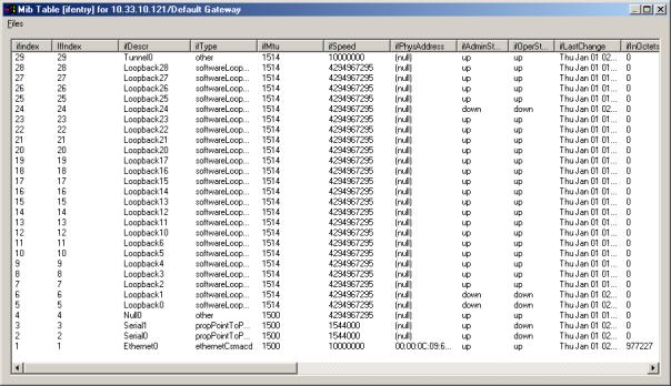
On this example it is easy to see that the router has an Ethernet 100 Mbps interface (index 1), two serial links working in point to point at speed of a T1 line (1544000 Mbps) owning index 2 and 3.
Remark: For those used to manipulate interfaces by the command line of the Cisco IOS, the interface number use by the IOS could be different from the index number use as MIB instance. This is a classical trick in many equipments.
|